
How to Split and Fragment a Large Rock Without Explosives
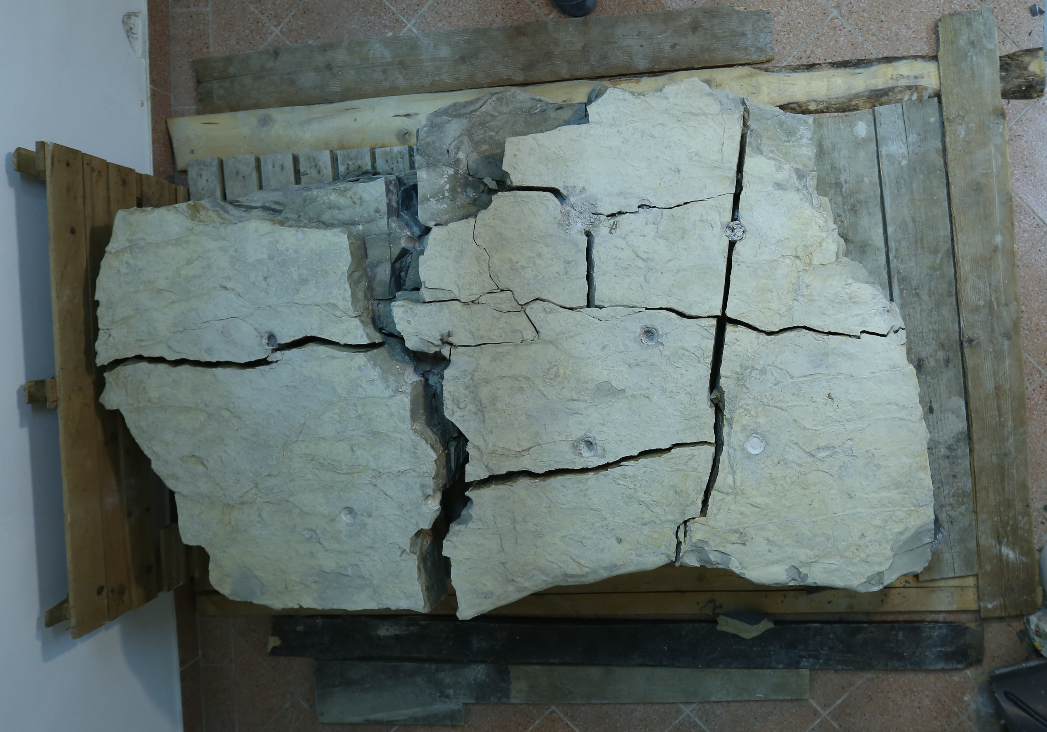
One Large Rock, Two Controlled Demolition Techniques
The purpose of this project was to demonstrate two different methods of breaking a large natural rock using FRAKTUREX® non-explosive demolition agent.
The rock weighed approximately 1.5 tonnes and was brought into a garage for a controlled practical demonstration. The project was divided into two stages. First, the complete rock was split into two large sections using a straight-line drilling pattern. The two sections were then fragmented into smaller, removable pieces using a different drilling layout.
The same basic drilling parameters were used during both stages. The difference was not the drill diameter or hole depth, but the arrangement of the holes and the intended demolition result.
Project Summary
| Project | Practical demonstration of two rock demolition techniques |
| Material | Natural rock |
| Estimated weight | Approx. 1.5 tonnes |
| Estimated rock thickness | Approx. 600 mm |
| Drill diameter | 35 mm |
| Hole depth | Approx. 500 mm |
| Stage 1 | Primary splitting using holes drilled in a straight line |
| Stage 2 | Secondary fragmentation using an adapted drilling layout |
| Demolition method | FRAKTUREX® non-explosive demolition agent |
| Final result | The rock was first divided into two sections and then reduced into smaller removable pieces |
The Objective of the Project
This project was designed to demonstrate how the selected drilling pattern determines the final demolition result. The same natural rock, 35 mm drill bit, approximate hole depth and FRAKTUREX® formula were used during both stages.
The first stage demonstrated how holes arranged in a straight line can create one principal fracture. The second stage demonstrated how an adapted grid pattern can generate multiple fractures and reduce the material into smaller pieces.
Stage 1 – Primary Splitting
Objective: Divide the approximately 1.5-tonne rock into two large sections.
The holes were drilled in a straight line. As FRAKTUREX® expanded, pressure propagated between the holes and created one main controlled fracture through the rock.
Stage 2 – Secondary Fragmentation
Objective: Reduce the two large sections into smaller pieces suitable for easier handling and removal.
The larger section was drilled using a grid pattern, while the smaller section required only one additional hole. The drilling layout was adapted to the size of each section.
Initial Rock and Project Preparation
Before drilling began, the rock was positioned in a controlled indoor work area. Its estimated thickness was approximately 600 mm, while the planned drilling depth was approximately 500 mm.
The holes were intentionally drilled shorter than the full thickness of the rock. This prevented breakthrough at the bottom while still providing sufficient depth for expansive pressure to act effectively inside the material.

Stage 1: Primary Splitting Along a Straight Line
The purpose of the first stage was to create one controlled fracture through the centre of the rock. A series of 35 mm holes was drilled in a straight line, with spacing selected to allow the cracks to propagate from one hole to the next.
FRAKTUREX® was then mixed according to the application instructions and poured into the clean, dry holes. As the material expanded, pressure gradually developed inside the rock and connected the drilled holes into one continuous fracture line.


Primary Splitting Drilling Parameters
| Drill diameter | 35 mm (1 3/8") |
| Hole spacing | Approx. 10 × drill diameter |
| Hole depth | Approx. 500 mm |
| Estimated rock thickness | Approx. 600 mm |
Primary Splitting Technical Illustration
The following technical illustration explains the actual drilling layout used during the first stage. It shows how a straight line of holes was used to create one controlled fracture and divide the rock into two large sections.

Result of the Primary Split
After the expansive reaction developed along the straight drilling line, the original rock separated into two large sections. This first stage was not intended to create small fragments. Its purpose was to demonstrate how a large rock can be divided accurately along one predetermined line.
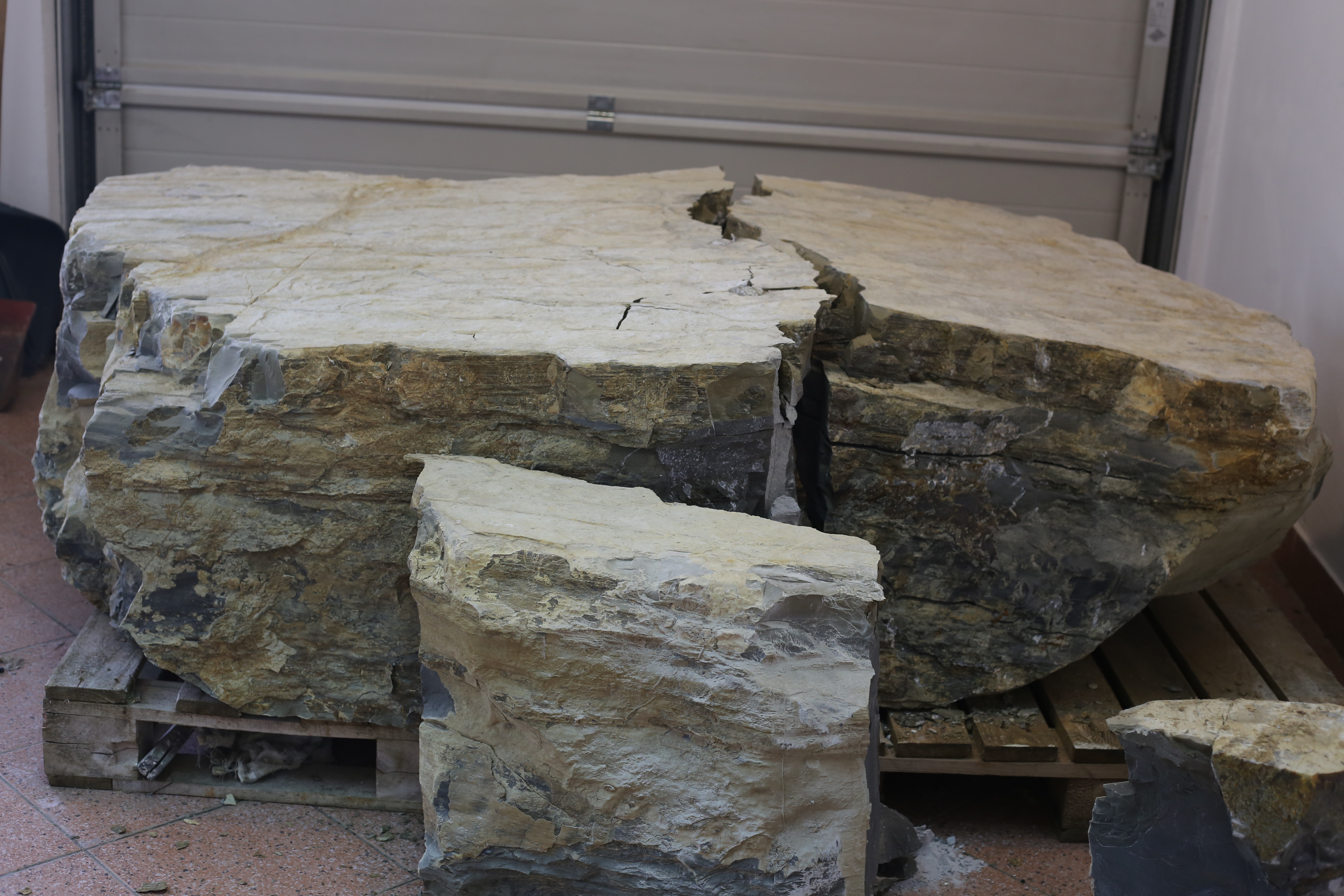
Stage 2: Secondary Rock Fragmentation
The second stage demonstrated a different demolition objective. Instead of creating one main fracture, the goal was to reduce the previously separated rock sections into smaller, manageable pieces.
The same 35 mm drill diameter and approximately 500 mm hole depth were used again. However, the drilling pattern was adapted to the size of each individual section.
Because the right-hand section was significantly larger, it was drilled using a grid pattern. This layout created multiple controlled fractures and allowed the section to break into several smaller pieces.
The smaller left-hand section required only one additional drilled hole. Due to its smaller remaining size, one FRAKTUREX® application was sufficient to complete its fragmentation.


Why the Drilling Layout Was Different
The second stage demonstrates why drilling patterns must be adapted to the intended result. A straight line is suitable when the goal is to produce one main split. A grid layout is more suitable when several fractures are required to reduce a larger section into smaller fragments.
The number and arrangement of holes should also reflect the size of the material. The larger section required a grid, while the smaller section could be fragmented with only one additional hole.
| Method | Drilling layout | Intended result |
|---|---|---|
| Primary splitting | Holes drilled in a straight line | One controlled fracture dividing the rock into two large sections |
| Secondary fragmentation | Grid drilling on the larger section and one hole in the smaller section | Multiple fractures producing smaller removable pieces |
Secondary Fragmentation Technical Illustration
The second illustration shows how the two previously separated rock sections were fragmented. It highlights the grid drilling layout used on the larger section and the single-hole application used on the smaller section.

Final Result
At the end of the project, the approximately 1.5-tonne rock had been completely reduced into smaller pieces. The final fragments were significantly easier to handle, move and transport than the original rock.
The project successfully demonstrated that the same non-explosive demolition agent and the same basic drilling parameters can produce very different results when the drilling layout is changed.

What This Project Demonstrated
- A large rock can be divided accurately using a straight-line drilling pattern.
- Previously split sections can be reduced further using a grid drilling pattern.
- Smaller sections may require fewer holes than larger sections.
- The drilling layout should always be selected according to the desired final result.
- The same drill diameter and hole depth can be used for different demolition objectives.
- FRAKTUREX® enables controlled rock splitting without conventional explosives.
Two Techniques, One Demolition Agent
The main lesson from this project is that successful rock demolition depends not only on the product, but also on selecting the correct drilling layout.
During the first stage, a straight line of holes created one principal fracture and divided the rock into two large sections. During the second stage, a grid pattern on the larger section and one additional hole in the smaller section produced multiple fractures and completed the fragmentation process.
Both stages used the same 35 mm drill bit and approximately 500 mm hole depth. The difference in the result was achieved by changing the placement and number of holes rather than the basic drilling parameters.
Together, the two stages provide a clear practical demonstration of how FRAKTUREX® can be used both for precision rock splitting and for final rock fragmentation.
Important Application Principles
- Use clean and dry drill holes.
- Remove drilling dust and loose material before filling.
- Do not drill through the full thickness of the rock.
- Select the drilling layout according to the desired fracture pattern.
- Use the correct FRAKTUREX® formula for the working temperature.
Planning a Rock Splitting Project?
FRAKTUREX® provides a safe, vibration-free and non-explosive solution for splitting large rocks into manageable sections and smaller removable pieces.
Choose the drilling layout that matches your demolition objective.